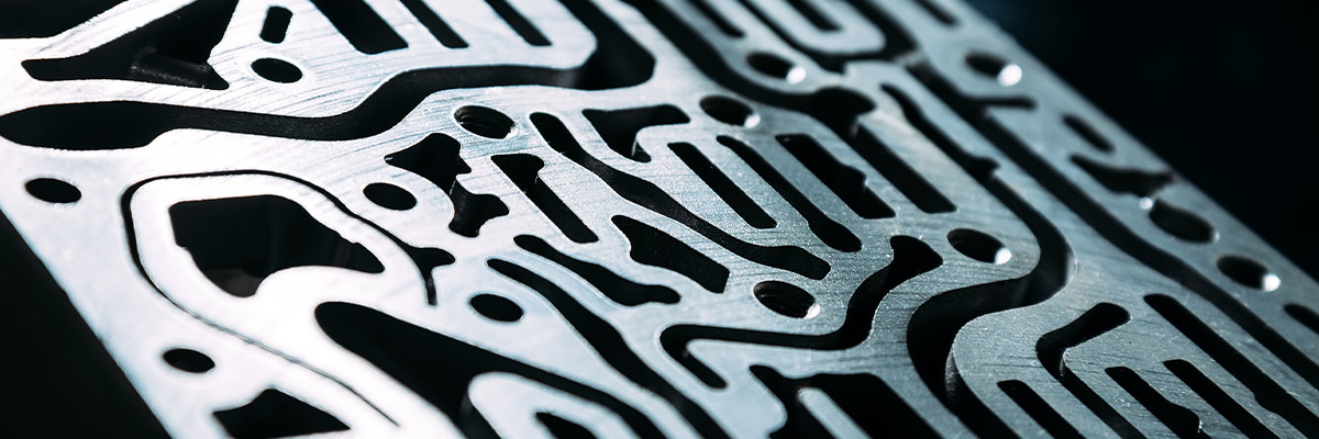
Metal 3D Printing and Additive Manufacturing

Functional metal parts — from prototype to repeatable series production.

On the EOS M290 and GE Additive M2 Serie 5 systems, we manufacture using DMLS / L-PBF (laser powder bed fusion) in AlSi10Mg aluminum alloy, 316L stainless steel, maraging steel, Inconel 625 superalloy and CuCp copper. We follow up with heat treatment, post-processing and dimensional verification for a turnkey solution under one roof.

Metal 3D Printing and Additive Manufacturing
DMLS / L-PBF (Laser Powder Bed Fusion)

A metal part is built layer by layer as a thin layer of metal powder is selectively melted with a laser and metallurgically fused to the layer beneath it. The build process runs inside an inert-gas chamber to prevent oxidation. With appropriate heat treatment, DMLS parts reach close to 100% density. The part’s density and fatigue life depend on the melt pool being consistent across every layer — which comes down to the machine as much as the process parameters.

We run two metal systems. The EOS M290 is one of the most field-proven L-PBF platforms, with high consistency for series work, while the GE Additive M2 Serie 5 is a dual-laser machine favored for fast, flexible production scenarios and a wider range of materials. Which system a part is built on is decided by material, geometry and quantity.

DMLS, SLM and L-PBF describe the same physics: fully melting metal powder with a laser. DMLS is EOS’s trade name, SLM is other manufacturers’ trade name; the ISO/ASTM standard name is L-PBF.

When Metal 3D Printing, When Machining?
Situation Suitable Method Why
Complex geometry, low-to-medium volume, consolidation/lightweighting Metal 3D printing No tooling or fixtures needed, design freedom, fast
Conformal cooling, internal channels, lattice structures Metal 3D printing Cannot be produced by machining
Simple prismatic part, high volume Machining / casting More economical per unit
Tight-tolerance & mirror-finish features required Hybrid: 3D printing + machining 3D printing forms the geometry, CNC machines the critical surfaces

For a simple, high-volume part, metal 3D printing is often not the right production method. We say so openly, and choose the right method together.

Materials and Selection Criteria

Mechanical properties (tensile, yield, elongation, hardness) vary with build orientation (XY/Z), heat-treatment condition and layer thickness; the figures below are approximate and non-binding. We agree on the target values that apply to your application during the quoting stage, and recommend sample testing for critical parts.

AlSi10Mg — Aluminum

Low density, high thermal conductivity, easy machinability and a high strength-to-weight ratio. Preferred for: lightweight brackets, heat sinks, manifolds.

316L — Stainless Steel

High corrosion resistance and ductility, weldability. Preferred for: parts in chemical, food, marine and medical environments.

Maraging (MS1) — Maraging Steel

Very high strength and dimensional stability after aging. Preferred for: mold cores and inserts, conformal cooling channels.

Inconel 625 — Nickel-Based Superalloy

High mechanical performance and corrosion resistance up to 600–650°C. Preferred for: aerospace, exhaust and combustion systems, chemical process equipment, marine and high-temperature applications.

CuCp — Copper

High thermal and electrical conductivity. Preferred for: thermal management, inductors, conformal cooling channels, mold cores and inserts.

Build Volume, Tolerance and Surface (EOS M290)

These figures are typical ranges depending on machine, material and process parameters; they are not binding or certified. We set target tolerances for your part's critical dimensions during quoting.

Build volume 250 × 250 × 325 mm
Layer thickness 20–60 µm (material-dependent)
Dimensional tolerance (as-built) ±0.1–0.2 mm or ±0.2% (whichever is greater)
Minimum wall thickness ~0.4–1.0 mm
Surface roughness (as-built) Ra: ~8–12 µm; reduced with post-processing
Critical surface tolerance Machinable on CNC; brought to tighter ranges
Design for Additive Manufacturing Rules (DfAM)

When you send us your 3D model file, we assess the part for manufacturability and come back with concrete revision suggestions.

Orientation Affects surface quality, the amount of support structure, build time and residual stress.
Support structures and overhang angles Surfaces below a certain angle require support structures; we orient the part to protect critical surfaces.
Internal channels and powder removal Self-supporting cross-sections are preferred; a powder-drain hole is planned for every enclosed cavity.
Machining allowance Tight-tolerance surfaces and holes are offset to leave stock for machining.
Residual stress and warping Large, flat, thick sections accumulate thermal stress during the build; cross-section transitions are radiused where possible and mass is distributed evenly.
From Production to Delivery
  • 1
    Manufacturability pre-check (DfAM)

    Orientation, support structures, surfaces to be machined and material selection are assessed before production.

  • 2
    3D printing and stress relief

    The part is built with DMLS / L-PBF; internal stresses are relieved by heat treatment before removal from the build plate.

  • 3
    Removal and heat treatment

    The part is removed from the build plate by wire EDM and support structures are cleaned off. Material-specific heat treatment (hardening for MS1) is applied.

  • 4
    Surface finishing and machining

    Blasting and, where needed, polishing are applied. Critical surfaces are CNC-machined, holes drilled and threads tapped.

  • 5
    Measurement and reporting

    A quality control report is prepared after measurement by 3D scanning or CMM. On request, a First Article Inspection (FAI) report and a Certificate of Conformance (CoC) are issued.

Post-Processing and Quality Control

The post-processing chain determines a part's mechanical properties, dimensional stability and surface. Our main capabilities:

Heat treatment Stress relief and material-specific heat treatment (hardening, aging), HIP and custom heat treatment.
Removal and cleaning Removal from the build plate (wire EDM), support structure removal.
Surface finishing Blasting, wet blasting, tumbling, polishing.
Machining 3- and 5-axis milling, turning, hole drilling/tapping.
Protection / appearance Passivation (stainless), anodizing (aluminum), coating and painting.
Measurement and documentation 3D scanning, CMM and profilometry; quality control report, FAI report, Certificate of Conformance (CoC).
Next step

Let's assess your part first.

Share your part's 3D model; with a manufacturability pre-check we'll pin down material, heat treatment, tolerance and post-processing recommendations, and map out a concrete plan. We typically get back to you within two business days.

COOKIE SETTINGS

This website uses cookies

We use cookies on our website to provide you with a better experience. For more information, please review our Cookie Policy.